 https://www.f1-consult.com/wp-content/uploads/2018/06/windows-2360920_1280.png
960
1280
wriedel
https://www.f1-consult.com/wp-content/uploads/2018/01/F1-Logo_trans.png
wriedel2018-06-25 01:36:142021-04-27 10:09:23How to Delete All VSS Shadows and Orphaned Shadows
https://www.f1-consult.com/wp-content/uploads/2018/06/windows-2360920_1280.png
960
1280
wriedel
https://www.f1-consult.com/wp-content/uploads/2018/01/F1-Logo_trans.png
wriedel2018-06-25 01:36:142021-04-27 10:09:23How to Delete All VSS Shadows and Orphaned Shadows http://packetpushers.net
https://www.f1-consult.com/wp-content/uploads/2018/06/PacketPushers.png
146
455
wriedel
https://www.f1-consult.com/wp-content/uploads/2018/01/F1-Logo_trans.png
wriedel2018-06-19 21:51:482021-04-27 10:09:23Network Operating Systems
http://packetpushers.net
https://www.f1-consult.com/wp-content/uploads/2018/06/PacketPushers.png
146
455
wriedel
https://www.f1-consult.com/wp-content/uploads/2018/01/F1-Logo_trans.png
wriedel2018-06-19 21:51:482021-04-27 10:09:23Network Operating Systems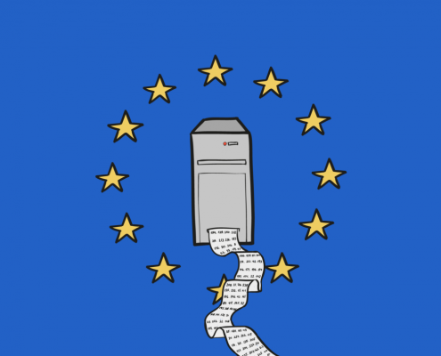 https://www.f1-consult.com/wp-content/uploads/2018/06/eu-gdpr-server-log-1408x792.png
792
1408
wriedel
https://www.f1-consult.com/wp-content/uploads/2018/01/F1-Logo_trans.png
wriedel2018-06-06 12:25:392021-04-27 10:09:23GDPR
https://www.f1-consult.com/wp-content/uploads/2018/06/eu-gdpr-server-log-1408x792.png
792
1408
wriedel
https://www.f1-consult.com/wp-content/uploads/2018/01/F1-Logo_trans.png
wriedel2018-06-06 12:25:392021-04-27 10:09:23GDPR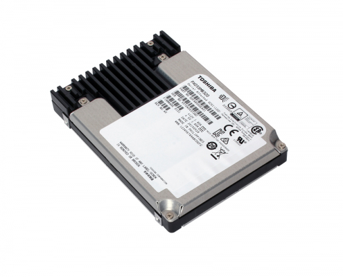 https://www.f1-consult.com/wp-content/uploads/2018/01/F1-Logo_trans.png
0
0
wriedel
https://www.f1-consult.com/wp-content/uploads/2018/01/F1-Logo_trans.png
wriedel2018-06-04 00:20:022021-04-27 10:09:23CISCO IOS and IOS-XE Call Routing
https://www.f1-consult.com/wp-content/uploads/2018/06/eSSD-PX05_1000px.jpg
667
1000
wriedel
https://www.f1-consult.com/wp-content/uploads/2018/01/F1-Logo_trans.png
wriedel2018-06-01 13:27:222021-04-27 10:09:23Solid State Drives Technology Comparison – SLC, MLC, TLC NAND
https://www.f1-consult.com/wp-content/uploads/2018/01/F1-Logo_trans.png
0
0
wriedel
https://www.f1-consult.com/wp-content/uploads/2018/01/F1-Logo_trans.png
wriedel2018-06-04 00:20:022021-04-27 10:09:23CISCO IOS and IOS-XE Call Routing
https://www.f1-consult.com/wp-content/uploads/2018/06/eSSD-PX05_1000px.jpg
667
1000
wriedel
https://www.f1-consult.com/wp-content/uploads/2018/01/F1-Logo_trans.png
wriedel2018-06-01 13:27:222021-04-27 10:09:23Solid State Drives Technology Comparison – SLC, MLC, TLC NAND